Sunday, February 27, 2011

Intake rerouting, brake ducts and plastic

I came home to a nice pile of boxes on 2/16.  The season is quickly approaching, so it's getting down to crunch time.  That being the case, it was time to get the trim pieces and other items to get the car looking complete.


As you're aware if you've been following along, the car came to me with a number of items missing from the front of the car.  Since I'd also updated the car to the 2009+ look, the bumper was missing all of it's trim pieces such as the grill, foglight bezels, etc.

This pile of boxes included the grill, front fender liners, under engine tray, and all of the associated fasteners needed to install them.  It's really amazing how all of these seemingly minutia pieces can add up in cost.


The stock foglight bezels really stick out on the car, and the side reflector is incorporated into the bezel.  I had previously ordered these, but decided that for my purposes, they didn't really seem like they were going to work right for my application.  While browsing images of MX-5 Cup cars, I noticed that they seemed to have a different bezel and found that they were brake ducts that could be purchased through Mazdaspeed.  What I didn't realize at the time was how expensive they were.  I had wrongly assumed that since the stock pieces were so cheap, that these couldn't be too bad.  Well, this was a case of not asking before ordering.  $200 later, they were on their way to me....  I was tempted to return them, but decided that ultimately they were really what I wanted, so in they went.

The ducts are made of fiberglass and have to be drilled and riveted to the car.  Good thing I've gotten fairly comfortable with drilling into the car, as I had to drill holes into my beautifully painted bumper....  For the time being I will just run them as is.  Eventually I'll probably add the hoses and backing plates to really use them for brake cooling.  However, since it'll be awhile before I put the car on the track, I'm not that concerned about it right now.


The other thing I decided to do was to take advantage of the headlight openings for the intake.  I had an AEM intake from my old CSP car that I had already installed.   This intake was deemed not legal in CSP because of the need to remove a splash guard, but for DP that didn't matter.  I figured that moving the filter to the passenger headlight opening would give it a cleaner air stream, so I ordered up a couple of rubber connector pieces and the associated clamps, along with a 2 foot long long piece of 3" aluminum tubing.  After looking at the intake for awhile, I determined that if I planned my cut of the existing tubing correctly, I could get away with just adding about 6-8" of new tubing.

After temporarily mocking it all up, I then set about trying to use the existing attachment arms.  Fortunately, those too were aluminum, so bending them to get them to where I wanted them was fairly easy.  I was able to use both of the existing attachments but attaching them to the car in different places. 


With just over a month before the first event, I've ordered the remaining three wheels from REAL Racing Wheel.  These guys have been a big help in my endeavor to fit 16" wheels to the car.  Not only do they build a great product, but their pricing, customer service, and build times are incredible in the custom wheel industry.  Their normal turn around time is about a week and a half to two weeks.  Their 16x10 wheels run about $365 each, which is a great price for a 3 piece aluminum wheel.  Once my Motons show up, I'll get everything mounted up and post more pictures.

I'll also be ordering up some wheel spacers, sway bars, end links,  race harness, shift knob, and a new seat mount and slider.  With these items and a quality alignment from Fordahl Motorsports, the car should be ready for it's debut.

More later.

Sunday, February 13, 2011

Test fitting new wheel

My updated wheel showed up with 7" of backspace instead of the previous 6".  Again as noted before, spacers will be needed to clear the calipers, so it made sense to move the wheel inboard.  I also had the center changed as you'll see in the pictures.

I had a tire mounted up and today I pulled the front and rear shock assemblies out to be able to lower the car to get an idea of how everything would look once the coilovers go in.  Again, I only have one wheel right now, so I apologize for the inability to see the whole side with two wheels.


Studs, hubs, and paint (Originally posted 2/12/11)

I just noticed that my last update was way back on Christmas day....
Work has definitely not stopped during that time, and in fact there have been some really big updates.
Since it’s difficult to find specific information on what works/fits these cars, I’m going to be including part numbers where I can to help others in the future.  It can be assumed that most numbers are Mazda part numbers.
First up, as noted previously, longer wheel studs needed to be done to fit the new wheels.  I had a couple of different choices since I will need spacers to fit the wheels.  First up would be the ARP studs that have a great reputation and the nice bullet noses.  The second choice was to get the Ichiba wheel spacers that come with longer studs.  The nice thing about the Ichiba spacers is that they are hub centric vs. normal spacers being more of a one size fits all.  Initially I decided to just get regular Gorilla spacers and so I chose to go with the ARP studs.  Again, they have a great track record (sorry for the unintentional pun there...) which was important to me.  After a bit of research, I determined that the correct ARP part number was 100-7719 for the studs.
Since I was replacing the studs, I also ordered up the 2009+ RX-8 front hubs. The RX-8 reportedly has beefier hubs than the MX-5, so this was a no brainer.   There are two different options for the hubs for the RX-8, one with DSC and one without.  I had previously ordered the one without DSC since my car didn’t have it and I assumed that would be the correct part.  As it turned out however, the ABS sensor mounting was incorrect on this one.  The correct part number is F189-33-04X. I had already replaced the right front upright with the 2009+ MX-5 part, so I ordered one for the left also.  The geometry had been updated on these newer ones to help with bump steer, especially when the car is lowered.  This updated upright/steering knuckle is NH42-33-030.

To replace the rear studs, the hub would need to be pressed out of the carrier, so I also ordered new wheel bearings for the back.  These are quite spendy, but now I have all new bearings front and rear, and as I found, these too are very beefy.  The part number for these are is FB01-26-151E.
Pressing out the “old” studs in the front was easy since the hubs just bolt to the uprights, so there is easy access.  The rears obviously are more challenging because of the need to press out the hub.  Since my car is a full on dedicated race car, I didn’t want to keep the brake backing plates, so I also removed those.  I cut them off prior to any of the press work which also made things easier when it came to pressing the bearings out and the new ones in.
 The Gorilla spacers were out of stock when I ordered the studs, so now I'm rethinking what to do for spacers.  I may get the Ichiba ones after all unless I can find something else hubcentric that isn't as expensive since I won't need the studs that come with the kit. 
After the intial fittings of the wheel from Real Racing Wheel, I decided to send my wheel back to get the backspacing increased from the 6” I had initially ordered to 7”.  I want to keep the wheels tucked in as much as possible, and with the need to run spacers to clear the brakes, I figured that it was easier to play with spacer thicknesses to get everything where I wanted it.  I’m going to wait until I get the suspension on the car before doing all of the final measurements, but I’m thinking that I’ll probably go with 15mm spacers front and rear with the 7” backspace.  The guys at Real were very accommodating in helping me with this.  A big shout out to these guys!
The next big thing I needed to do was to refit the carbon fiber doors and get them aligned correctly.  I also needed to figure out a way to secure them in the closed position that would allow for easy opening.
I’m keeping the stock hinges on the car, and the alignment is mostly determined by the way the hinges mount to the body of the car.  The holes on the door side of the hinge are only big enough for the bolt.  This required pulling the fenders to get at the bolts on the body side of the hinge.  I was able to get most of the adjustment I needed by doing this, but the fine tuning required some grinding and dremeling…  I ultimately had to grind down part of the lower hinge to allow the bottom of the door to tuck in like it should and also had to enlarge the lower hole.  In stock form, each of the hinges has two bolts that go into the door.  Since the carbon fiber doors are WAY lighter, I chose to only use the top and bottom bolts.  Two bolts don’t really save much weight, but every little bit helps.
As for securing the doors, I had been thinking on this one for a few months.  Early on I thought about going with the Aerocatch latches as those would allow me to open the doors from the outside and they would definitely have a cool factor.  However after taking a closer look at the doors and the door frame, I decided that while it might be doable, it would take a lot of work.  I finally got an “a-ha” moment while at work.  I’m a UPS driver by trade, and while doing my morning pre-trip, it suddenly dawned on me that I could do something similar to the way the hoods are secured on our trucks.  It’s a basic rubber strap hard mounted on the bumper with a ball at the other end that mounts into a receiver that’s attached to the hood.  I went to Lowe’s (our local big home improvement store) to see if I could find something similar.  It turned out that they didn’t have what I was looking for, but one of their associates suggested I try a 4 wheel drive place since Jeep Wranglers and some of the Range Rovers use something similar.  Unfortunately it was late on a Saturday and we don’t have any 4 wheel drive places close.  In explaining this to my wife, she suggested we try our local Arctic Cat/Kawasaki dealer since they were close by.  That didn’t make much sense initially, but all the sudden a light bulb in my head went super white!  During the winter months I spend a lot of weekends snowmobiling.  For anyone that’s ridden a snowmobile, you know that the hoods on those are held down with a very similar setup to what I was thinking of.  Why this hadn’t popped into my mind earlier, I don’t know.  In any case, we hopped over there and explained what we were looking for to the parts guy and he brought out a few different options.  One of them looked like it would work, so I purchased the parts for a whopping $15 and brought them home.  I drilled a hole in the door frame for the fixed end and then drilled two holes into the door for the receiver bracket.  I used rivnuts in the door to make the bracket easily removable, plus the rivnuts are probably a little stronger than using regular rivets.

Speaking of rivnuts, I’ve been using them a lot.  The main thing I’ve used them for is the routing of the wiring.  I was able to shorten a bunch of wires and reroute some to minimize the number of locations where I have wires running.
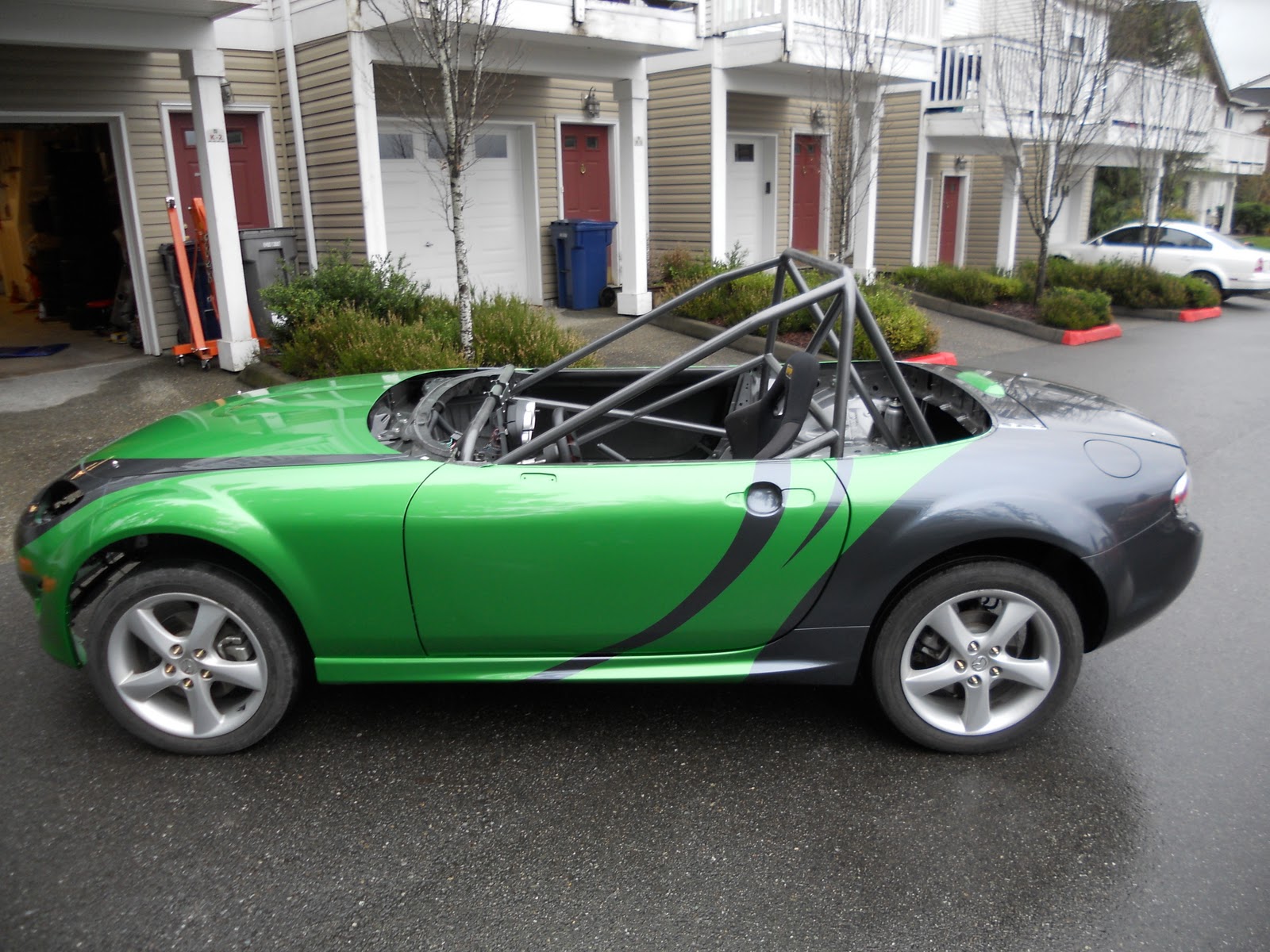
The coolest thing just happened this past Saturday though.  We took the car in to Pacific Auto Body and got it painted.  We went with a two color scheme utilizing some GM colors.  The inspiration for the paint scheme came from a European race series.  Initially when thinking of what color to paint the car, I had intended to just do a single color and then add graphics.  I wasn’t sure what color I wanted until I saw a new Camaro in Synergy Green Metallic.  At that moment, I knew that was the color for me, but for awhile had changed my mind and was thinking of going with Mexico Blue, which is a classic Porsche color.  I was set to go with that, but then we attended the Seattle Auto Show, where they again had a Synergy Green Camaro.  Sold!
 After determining the paint scheme we wanted to go with, the next decision was what the second color would be.  Since we were already using a Camaro color, I decided to see what gray colors were available on the Camaro/Corvette.   I saw pictures of a few Corvettes in Cyber Gray Metallic and it looked like a great second color.  We then went to our local dealer to see if they had touch up paint in the two colors.  Unfortunately they didn’t.  They did however have a Cyber Gray Corvette.  Beautiful!  As luck would have it, I went to another Mazda/Chevrolet dealer to look at MX-5s and the difference between stock and appearance package side skirts.  Guess what was there?  Two Camaros parked right next to each other, one in Synergy Green and one in Cyber Gray.  That made the final decision easy.
Pacific Auto Body is a Seattle shop that specializes in BMW, Mercedes, and a number of other cars.  They did an incredible job on our car, and I wouldn’t hesitate to send anyone there for paint and/or body work.  A lot of work went into getting the car painted, as all of the existing paint had to be sanded down, the plastic rear bumper had to be specially treated to allow the paint to stick, etc. 
The car was originally black, to which I added carbon fiber doors, a white front bumper, blue front fenders, a black primered rear quarter panel, and a black plastic rear bumper.  Obviously a lot of different colors were going on.  After sanding everything down and primering the carbon doors, a base coat of white was sprayed to allow the green to “pop” correctly.  The car and parts were then masked to do the gray over the top.  What you see is the finished product!  Again, a big thanks go out to Pacific Auto Body, and especially Jerry and Kyle who did the work.


So that mostly catches us up.  Next up is to get the suspension on the car, order up the other wheels, and get a few other items.
Talk soon.

16x10 REAL Racing wheel shows up! (Originally posted 12/25/10)

As promised, my wheel showed up today and I did an initial test fitting tonight when I got home from the requisite Christmas Eve family function.

The first thing I did when I pulled the wheel out of the box was to weigh the wheel. It seems a bit heavy at around 17 pounds, but is certainly robust. It's also a nice looking wheel.

I then took it down to the garage and pulled a front and rear wheel for initial fitting. As previously noted, the two original wheel makers I had talked to (Diamond Racing Wheels and Spinwerks) said their wheels wouldn't fit over the stock brakes, so this was my first concern. The other big concern was whether the wheel would fit over the lower link on the rear suspension.

I mounted the wheel first in the front. It definitely clears the calipers and seems to be a pretty good offset, however due to the shape of the center of the wheel, it will require a spacer of approximately 3/8" (5 mm) to clear the caliper carrier.

Next up I moved it to the rear. It bolted up and appeared to fit completely. However, once I took the e-brake off and tried to spin the wheel, I noticed that it didn't turn as well as it should. I got under the car and took a look at the brakes and the lower link and all of them had clearance. So, the only issue in the back is the same as the front where it will require a spacer, although it would only need a very minimal spacer in the back.

Again, the biggest issue I was concerned about was the lower link in the rear. Let's just say the clearance is tight.... There is only about 1/8" between the link and the wheel! The main thing though is that it does fit!


Next up, I'll have to get some spacers and obviously longer studs. I'll also get one of my tires mounted up and do further fitting to verify everything is good.


More later.

Tires for the Beast (Originally posted 11/13/10)

I picked up a used set of tires this morning for the car. The size I'll be running are 23.5x11x16 on 16x10 wheels.

So, I put them under the rear fenders and lowered the car down with the jack until suspension was resting on the tires. Hopefully I'll be able to lower the car even further once the suspension and wheels are on, but this is a good starting point for showing how much rubber will be under the car.

I also ordered up a new rear bumper from the '09 up cars so that the car will have the look of the newest version. BTW, if anyone has a '09 up and has a spare pair of stock sideskirts sitting around, let me know. I'm in need of those as well.

More weight loss and gauge panel (Originally posted 12/20/10)

As I noted in my last post, I was working on removing the sound deadening material from under the seats and on the rear deck.  All in all, I pulled out around 4.5 - 5 pounds of material doing this.  I thought about pulling out the stuff in the footwells, but because it was so thin and covering a number of overlapping panels, I decided that I'd just paint over that stuff.

The cage is now full painted in black Hammered, and I just finished painting the interior in grey Hammered.  

I've also been continuing to work on the wiring in the car.  During some slow time while I was waiting for paint to dry, I decided to get rid of the wiring in the front of the car for the headlights.  It needed to be done, but what started as a nice "simple" idea turned out to be a LOT more.  I decided that rather than just cutting the wiring out, I would pull out the pins at their origin.  In most cases this was at the fuse block.  Of course while I was in there, I couldn't stop at the part I was working on.  Next thing I knew, I had pulled out a bunch of wiring.  In the end, it's worth it to have simplified the system, along with taking away the worry of something shorting later because of cut wires.  One of these days I’ll get around to weighing all of the wiring I’ve pulled.

Since the 2011 season will be here before I know, I'm starting to move to the more serious (read, expensive....) items.  The two major items are wheels and suspension. 

In my quest to find 16x10 wheels, I purchased a tool to help me determine the proper backspace for the car.  The tool effectively allows you to see where there might be fitment issues as it attaches directly to the hub and can be rotated through the full arc.  Using this, I determined that a 6" backspace would be a good starting point.  Since I'm apparently the first to try to fit 16x10s, I wanted to order up a less expensive wheel to start with to make sure my measurements were all good.

Unfortunately, the first two companies I contacted told me their wheels wouldn't fit with that backspace.  Apparently the drop centers wouldn't fit over the brakes with this offset.  The second company said their wheel might fit with a 5" backspace.  Moving the wheel out that far would not only probably require flares, but it also would create a rubbing problem with the seams at the back of the front fenders.

A couple of people recommended that I contact REAL Racing wheels.  I checked out their website and talked to them and it sounds like their wheels should work.  I have a wheel on it's way to me and should be here on Christmas Eve.  My fingers are crossed that it will fit.  Once I verify fitment, I'll get one of my tires mounted up to do the final verifications, and then can order up the remaining 3.

I'm also finalizing my research on suspension.  At this point the front runners are AST and Moton.  Both companies now offer double adjustable shocks without remote reservoirs at a lower price point.  I've heard very good things about the ASTs and my previous experience with Motons on my CSP MX-5 was quite good.  I should be making a decision in the next week or so on this.

In the meantime, I needed to put together a gauge panel of sorts for my ignition/start switch and the factory gauges.  After mounting my new steering wheel (a 320mm no-name wheel,) I realized that my initial thought of just mounting the gauge cluster in more or less the stock spot wasn't going to work.  First of all, one of the attachment points would have been to the cage.  I soon realized however that using the tilt function caused a problem with the mounting to the cage.  I also quickly realized that I couldn't properly see the gauges through the smaller wheel.

After moving the cluster around, I decided that just mounting to the new center panel I was planning to install was the best option.  Eventually I'll hopefully be able to get rid of the stock cluster, but for now, I need to keep it for the car to run.

I'm reusing two of the holes in the transmission tunnel that the stock dash originally mounted to and then have purchased a couple of brackets from Longacre Racing that go around the front hoop of the cage for the upper mounting points of the panel.  I used 1/16" aluminum angle to form the side brackets and then picked up some 1/8" ABS plastic for the panel.  It measures 9.5x15. 

I had previously purchased a rivnut set for a previous project so this seemed like a great opportunity to use this awesome stuff.  For those that don't know what a rivnut is, it's very similar to a rivet.  However, instead of the rivet going through both pieces that are being joined, the rivnut only goes into the back portion.  The beauty of it is that the inside of the rivnut is threaded so that you can put a screw through the front portion to join it to the back piece.

Since this panel will probably need to come off at times, either for putting other gauges in or replacing it later with something cool like carbon fiber, I felt it was better to use the rivnuts instead of rivets.  Not only is the ABS now screwed to the brackets, but the ignition/start switch and gauge cluster are screwed to the ABS.  One other thing that I couldn't have planned better if I tried is that the brackets turned out to be the perfect width to still be able to plug the wiring into the back of the gauge cluster.


The first picture shows the left bracket with holes drilled for the rivnuts, while the right bracket has the rivnuts already installed.  The second picture shows the the panel attached with the ignition/start switch already in place.  You can see the rivnuts in place for the gauge cluster in this pic also.  I mounted the cluster using three existing bolt holes.  The final picture shows it installed.  It doesn't look super cool, but it has to be in the car at this point and it's solidly mounted and in my field of vision.

The next update will hopefully have great news of the wheel/tire fitting the car!  Stay tuned.

Saturday, February 12, 2011

Been awhile (Originally posted 10/26/10)

It's been awhile since my last post. I guess life has gotten in the way.

It's not to say I haven't been working on the car at all, just been slow going.

Since the last post:
- Got new set of carbon fiber doors and have them temporarily mounted. Still need to get a nice day on a weekend at home to pull the car out of the garage to hang them correctly. I still also need to figure out how I'm going to keep them closed.
- Picked up a front bumper cover from a 2010. Now I've got a white front on the already blue, black, and flat black car...  The bumper was naked, being just the cover. So I've ordered up the brackets to hold it on and the foglight housing.
- I'm currently working on the removal of the sound deadening material that is under the seats and on the back deck. I've already done the back deck and passenger side, and am about half way through the driver's side. It started from my plan to paint the interior and not wanting to paint over it. As it turns out though, it's pulling out about 2 pounds per location. Not insubstantial in the grand scheme of things. The steps involved include - Using a scraper/putty knife to pry it out (this is slow and tedious!) - Go back over the area a second time with the scraper to get as many of the small chunks off - Finally go over the whole thing with Acetone to remove the remaining residue.


I'll try to post more this weekend

Painting the cage (Originally posted 9/18/10)

I picked up a can of Hammered today along with a couple of foam rollers to go with the foam brushes that Alyson (my wife) picked up for me yesterday.  I had been trying to decide between black and gray and was leaning towards the gray.  However, after visiting numerous stores, no one seems to carry the gray.  So, black it was.  I’ll be ordering up some gray for the remainder of the interior.

Rustoleum advertises this product as a “Unique hammered finish that stops rust and hides surface imperfections.”   The only downside to this product is that you have to be careful applying it because it will create strings as it quickly starts drying.  You have to go under the assumption that you’ll be doing a 2nd coat and only go over each spot once.  The 2nd coat has to be done within 4 hours, otherwise you have to wait 7 days.  I’ll be waiting due to a shortness of time today.

So far it’s turning out beautifully.  Although the color is called black, it turns out dark gray. 


The other development is that I had purchased what I thought was a new passenger side piece that mounts to the engine and the motor mount on the other side.  The piece itself is aluminum.  The one on Bruiser had one of the tabs missing where it’s bolted to the engine, thus the need for a new one.  Unfortunately the mount that I received was for the driver’s side.  I’ll have to re-order the correct  one.

Cage is in (Originally posted 9/15/10)

Day 3 Creations finished up the cage today, so now Bruiser is back home. Derik of Day 3 did a great job building the cage, with beautiful welds and bars going to the rear as well as front shock areas.

SCCA Solo rules give two options on Prepared cages. There is a specific set of options to build a cage in the Solo rulebook, but it is strongly recommended that the cages be built according to the GCR (General Competion Rules - aka SCCA Roadracing rulebook.) That being the case, I went with the second option. It does make the car a little harder to get into with the extra bars tying the rear hoop to the front, but from both a strength and safety standpoint, it will be worth it.

Because the stock steering column on our MX-5s is adjustable for height, the cage builder cut out the portion of the dash bar that contained the column mount and attached that to the cage with two additional tubes. So, I still have the ability to adjust the column for height same as stock.

Next up is painting the cage. I'll be using a Rustoleum product called Hammered which provides both rust protection and a hard surface.


Quarter panel replacement and carbon fiber doors (Originally posted 9/5/10)

What a hectic week at work.  My plan had been to get the spot welds all ground down during the week and get the quarter panel put on.  As it turned out though, I was working until 8 pm most nights.  Fortunately, like most others out there, Labor Day means a long weekend, so I was able to get a lot done.

First up was grinding down the rest of the spot welds.  This was easily and quickly accomplished with the electric grinder that I borrowed from a friend.  I had picked up a spot welder at Harbor Freight to put the new quarter panel on, but after deliberating for a while, and realizing that there weren't a whole lot of places that I could actually get to with the spot welder, I decided to forgo the spot welding and just rivet the whole thing on.  My original plan was to rivet the spots that I couldn't get to with the spot welder anyway, so it wasn't really a huge change.  Since it's a race car anyway, I wasn't worried about the fact that it wouldn't look 100% factory.  Once I got the panel on it was easy to see what needed to be done to get the dented portion to match up with the new panel.  A little work with the BFH and all was good...


As I posted previously, I also ordered up some carbon fiber doors.  They arrived, but unfortunately were damaged.  I got the okay to temporarily install them to take measurements for the cage.  They are a really sweet setup though.  The shipping weight for each door was only 11 pounds.  I pulled the stock passenger door off today, keep in mind I had already removed the windows, speakers, interior panels, etc., and the door weighed 32.5 pounds.  So, each door is saving over 20 pounds from the weight of the car!


I've also gotten a good start on cleaning up the wiring.  Eventually my plan is to get rid of the wiring from the interior connector plugs to the fuse box, but that will have to wait a little while.  Meanwhile I've removed an amazing amount of wiring and learned a lot about how much there really is in our newer cars!

The car is again looking almost whole.  I had recently sold off the front bumper cover to the same person that bought the headlights.  Once I realized that the selling of the headlights meant that I didn't have to go with a 2006 front end, I decided that getting rid of the bumper in an effort to get a bumper from a 2010 to make the car look like the current model made a lot of sense.  I'm also thinking about updating the sideskirts and rear bumper as well while I'm at it.  If anyone is in the market for a rear bumper cover, let me know.

My excitement is definitely going up with each of these steps.  Tomorrow morning the car goes into the cage builder.  I have Day 3 Creations (www.day3creations.com) doing the work.  I'll post more pictures once this is in!

Body updates (Originally posted 8/29/10)

Now that the car moves under it's own power, it's time to start doing some of the other big stuff.

For those following along, the car had some cosmetic damage to the drivers door and rear quarter panel. Since there was a nice big hole cut in the quarter panel, the only option is to replace the whole thing. So, ordered up a new panel from Mazdaspeed Motorsports. It comes complete with the gas filler hole already attached, so that makes things a little easier.


First up is the removal of the old quarter panel. These panels are spot welded to the rest of the car, so I purchased a spot weld cutting tool. It's basically a really small hole saw that cuts around the spot weld. Once you've done this with all of the spot welds holding the panel to the car, you can easily remove it. Next up you then have to grind down all of the raised portions. This doesn't necessarily sound that hard, but with there being approximately 40 spot welds holding the panel on, it's very time consuming. As it turns out, the quarter panel also is held on with quite a bit of seam sealer, so it was a little more challenging than I expected. Since I only have a battery operated grinder, I'm spending a lot of time waiting for the batteries to recharge. Hopefully I'll be able to get this all finished up tomorrow or Wednesday and be ready to start fitting the new panel.

The other exciting news is that I ordered up a pair of carbon fiber doors. I needed to replace the driver's door anyway, and the passenger door had a few dings from it's high mileage life, so this seemed like a smart way to go. They are supposed to arrive tomorrow, so I'll be sure to document this awesome development and post it!

Once these items are all in place, the car is going in for it's rollcage. Again, pictures will be forthcoming.

Stay tuned, it's starting to get exciting!

Clutch finally working plus first drive as a manual (Originally posted 7/4/10)

I finally got the order placed for the last few items I needed to get the clutch working.   The plan was to get them in time for the long 4th of July weekend, so I could have everything ready for when the slave cylinder finally arrived.

 As luck would have it, when checking the status of the order on the new parts, I noticed that the slave cylinder had finally shipped as well!  The slave arrived first, so I installed that and put the lower hard line on to determine where everything bolted up.  The next day, the bracket, extra bolts, and master cylinder reservoir showed up.  I only had a small amount of time that night, so I installed the bracket and finally had all the lines in place.  As the picture below shows, the new reservoir came with new seals and a new pin that holds the reservoir to the master cylinder.  Interestingly, the reservoir has a blue tint to it.  I’ve included a couple of pictures showing the difference between the two reservoirs along with how it’s attached.  It’s actually a pretty slick setup.  The pin holding the old reservoir on came out fairly easy using a punch and a hammer to get the pin about halfway out, and then pulling it out the rest of the way with a pair of vice grips.  Putting the new reservoir on was a little more tricky.  First up, the seals need to be placed on the reservoir first and then the reservoir can be pushed into the master cylinder.  Getting the pin pressed through was more challenging.  I had to squeeze one end first to allow it to fit in the hole, and then ultimately used a small torx bit to use as something to hammer against.

Next up, I attached the flexible line from the clutch master to the master reservoir and filled the master with Motul brake fluid.  Rather than just bleeding the clutch slave, I went ahead and took the time to bleed the brakes and get fresh Motul in the whole system.  I have a nice bleeder that uses compressed air to suction the fluid through, so it’s an “easy” one man job.  I took my time to make sure that fresh fluid made it’s way through.  After doing all of the brakes, I hooked it up to the clutch slave and after a few moments, fresh fluid came out.  I closed it up, got in the car and felt the best feeling so far, the clutch pedal seemed to actually work.  After a few pumps, I went back down and bled a little more fluid through for good measure.

Next up was some cleanup around the car, putting the wheels back on and lowering the car to the ground.  We set the camera phone to video, and recorded the first drive of the car as a 5 speed!  Since the car is far from street legal now, all I could do was drive it around our townhouse complex.  I don’t think my neighbors appreciated it, but I wound it up a bit in first and second and it seems to run great.

Particularly funny was when I started pulling it out of the garage and realized that having the key in the ignition was good for another reason…..  While turning out of the garage, the steering lock engaged.  Oops.  A quick turn of the key and I was off.


Now I’m working on cleaning up the wiring in the passenger compartment.  The most challenging part is figuring out what is needed and what isn’t.  While the wiring diagrams are very helpful, I’m working it a little different.  Basically I’m trying to go connector by connector to figure out what I need from each of the connectors.  What I’ve decided will work best is to write down each of the wire colors in each connector and then trace them in the diagrams to determine what each one is for.  It’s a lot of work, but ultimately it will make the job easier.  As you can see from the picture, I have a big mess of wires right now.  I picked up some heat shrink tubing along with other tubing to put the finished wiring in. 


I also put hood pins on the front of the car.  I purchased aluminum ones and have done the front so far.  I placed the pins where the stock rubber stops go.  There is a nice flat spot where these meet the hood, and the holes were a good size to put the pins through.  Also, this made drilling through the first layer of the hood since there was an obvious point where the bump stops hit that portion.  For the top portion of the hood, I snugged the pins down and then put a dab of whiteout on the top of each one and closed the hood on them to allow the whiteout to transfer.  This showed me where the center of the drilling point needed to be.  After drilling the holes to the appropriate size, I put the round aluminum protectors in place and riveted them to the hood. Lastly, I cut the tops off the bumpstops and placed them over the pins to allow the hood to still rest on the rubber.   Next up is the trunk lid, and I hope to finish that up today.  I did pull out all the latches for the hood and trunk lid, and it does save a little weight.  More importantly, it’s less work to get into the car at each end.

5 speed install and the car still runs! (Originally posted 6/24/10)

Since the last update, a lot has happened.

Most of the parts needed to do the transplant came in. Unfortunately the clutch slave cylinder is on national back order, so the car doesn't yet move as a manual transmissioned car yet, but....

As noted before, I had to order a new differential mount (the arms portion - for those that don't know, the NC has a separate pumpkin and arms) because there were different part numbers for the automatic vs. the manual. I assumed the difference to be a minor front/rear relocation of where the pumpkin was in relation to the transmission. Well, when I received the new one and did some rough comparing of the two arms, it appears that they are the same with the exception of one being stamped MT and the other being stamped AT. In fact the part numbers on the arms themselves are the same. In talking to Mazdaspeed Motorsports, they said that sometimes the only difference is the durometer of the bushings. So, it turns out I could have probably used the existing one. On the plus side, I now have new bushings in this new mount vs. the 99,000 mile ones in the old one. Plus I have a spare. For a Prepared level car, spares are always good. So, I paired the LSD pumpkin with the new mount and put it in the car.

A couple of the other differences between the automatic and manual cars were the radiator and pilot bearing in the end of the crank. Again, thanks to fellow forum member Jim Boemler for the radiator from his car. The fan unit mounted right up, and all of the hoses still mount the same. The pilot bearing was a fairly simple install, just needing a similar size socket to use to "push" it into the crank with the help of a hammer....


With these items done, I installed the transmission along with the corresponding drive shaft (again, there are different drive shafts for the automatic, 5 speed, and 6 speed transmissions since the lengths needed are all different,) the power plant frame, and the remainder of the exhaust. I previously installed a Goodwin Racing header, but currently only have the stock midpipe to mount between that and the Goodwin Racing muffler. Since I will be well under weight, I'm not as worried about how heavy the exhaust components are since the weight will be down low. Also, I'll probably need more weight in the rear of the car, so having a full size muffler will help in this regard while also keeping the sound hopefully low enough to pass sound at any site.

A bit of a shocker was when I received the parts and noticed that I didn't receive the brake pedal assembly that I'd ordered. The paperwork/invoice I received had a handwritten notation next to the part number that read “O/S.” My worry was that this meant out of stock. I called Mazda the next morning and they did some research and informed me that it really meant “offsite.” This was a good thing because it was supposedly the last one in the country. Of course the bigger issue was that it was supposedly delivered before the other parts were and I never saw it. So, more research showed that for some reason it went to an old address. I sent my wife over to that address and fortunately it was still sitting outside. Whew.

Pulling out the automatic brake pedal cluster was fairly easy, with just one cotter pin and four nuts. The new one went in just as easy and the clutch pedal went in smoothly as well. The hole is already in the firewall for the clutch setup, so all that was required was putting the clutch master cylinder through and mating it to the clutch pedal assembly.

Now is where another difference was noted. The brake master cylinder (which houses the fluid for the brakes and clutch in a manual transmissioned car) has a different reservoir for the automatic. Missing is the nub to attach the fluid line that goes to the clutch master cylinder. Fortunately the rest of the brake master cylinder is the same, since a new reservoir is only about a quarter of the cost of a full master cylinder. So that will need to be ordered.

Next up was to install all of the clutch lines. I went with all stock stuff except for the flexible line that is in the middle of the setup. For that line I purchased a stainless braided line from Thompson Automotive. The cost of that versus the stock rubber unit was comparable, and this will avoid possible flexing of the line that the stock rubber one might have had. I did unfortunately order one part wrong. There are two brackets that are used for the mating points between the hard lines and flexible line. For whatever reason, I ordered two of the top one rather than one top and one bottom. So, that’s now added to the parts cart.

So, the car theoretically is only this bracket, the master cylinder reservoir and a slave cylinder away from moving on it’s own. Obviously it will require putting all new brake fluid in and lots of bleeding.

Now is where it gets interesting…

After putting the “new” radiator in and installing everything else, I decided to try starting the car to see if it ran with the automatic ECU despite not having an automatic transmission. So, ignition on, check. Engage starter, DENIED! It wouldn’t turn over at all, no clicking, no nothing. Yikes. Did I finally do something to kick the immobilizer into effect (even though I thought I already removed that portion?) Oh, I know, let me check to make sure all the wiring is attached to the starter still. Oh, look at that, I forgot to reattach the bracket that had the Ground. Okay, so reattach that. Huh, still won’t turn over.

The automatic transmission had a “transmission range switch” in it that told the ECU if the car was in either Park or Neutral. When I took out the transmission, obviously this went away. It’s similar to the clutch switch on manual transmissioned cars. The computer doesn’t want you to try to start the car when it can move under the power of the starter. Great for street cars, not necessary for race cars where the driver is hopefully smart enough to have the car in neutral anyway.

I wasn’t positive that this was the reason for the car not turning over, but I decided to try another route to start the car. Since the clutch isn’t yet functioning in the car, I couldn’t bump start the car. That left engaging the starter directly as the next course of action. The starter on the NC is pretty much the same as every other Miata, with a big wire coming directly from the battery for main power and then a smaller wire going to the solenoid that is switched power. My timing light kit that I had bought a long time ago had a remote starter included, so that looked like the logical next step. The remote starter has one end attach to the battery or other power, and the other to the solenoid on the starter. You then push a button to (hopefully) engage the starter. Sounds easy, but, it didn’t turn out quite so easy. I assumed that pulling that switched power wire off would be easy. Problem was, I couldn’t find the release on the end. It’s also right above the main power wire. I unbolted the main power wire hoping that I could find the release, but that didn’t help. I finally gave up and pulled the starter out of the car altogether in order to pull it off. With that done, I hooked up the remote starter, bolted the starter back in and reattached the main power wire. I crossed my fingers, reconnected the battery, turned the key to the “on” position and hit the remote starter button. Wala! It started right up.

As near as I can tell, the car runs perfectly, even though I currently have the O2 sensors hanging since they don’t have any holes to bolt into yet. They originally bolted into the stock header, one before and one after the cat. I will likely be getting a Goodwin Racing midpipe which has the bungs, so that will solve that. Once I can get the car back on the ground and can drive it around our complex, I’ll know a little more.

This was great news that I could start the car directly. I decided to order up an ignition and starter switch panel from Longacre Racing. The piece I purchased is weather tight which will obviously be needed in an open car. It has a toggle switch for the ignition and a button for the starter.

My next big hope was to be able to run the ignition through this switch and therefore eliminate the need for the the key and ignition assembly. After studying the wiring diagrams, I determined the wires that were necessary to run the ignition through the switch. After some cutting and splicing the moment of truth came. I turned the switch on and the instrument cluster lit up, pushed the start button and Woohoo, the car started right up.

Of course as I was writing this, I realized that when I had done this, the key was still in the ignition. Oh crap. I pulled the key out, and now the car turns over but doesn’t start. Put the key back in, it starts. Okay, back to the wiring diagrams.

I’ll do some research and see if I can figure this out. Obviously the keys are coded to the car, but I’d really like to get rid of the key. I even purchased hood pins from Longacre so that I don’t need the key for the trunk lid.

To be continued…..

A little cleaning - and spoiler removal (Originally posted 6/7/10)

While I wait to get the parts I need to put the transmission and LSD in the car, I’m working on doing some cleaning.  As everyone knows that has ever worked on a car, it’s always much easier and nicer when the car is clean.  Since all of my other MX-5s were new, they were super clean and easy to work on.

This car however, has about 95,000 miles on it, and thus has accumulated a lot of dirt, sand, and other muck.  The front is pretty nice under the car because of the new subframe and right suspension pieces, but the rear isn’t so nice.  So, tonight after cleaning up my Goodwin Racing muffler, I started on some of the parts I’ve pulled off the car.  First up was the powerplant frame followed by the rear hubs which are already off of the car to do the differential swap.  Next up, I got under the car and started brushing off the grit figuring that I could clean the multi-links and subframe while they were in the car.   This lasted all of a couple of minutes.  I think we’ve all cleaned things in this fashion and there are always missed spots.  So, I decided to just pull off the subframe and then take off each of the links.   This way I’m able to clean everything much more thoroughly.  Additionally, this will allow me to clean the unibody properly.  So, I got the right side links cleaned and will finish the rest of the parts over the next couple of days.


Since I’ll be putting a “proper” rear spoiler on the rear decklid, I had to take off the stock spoiler.  I spent last night working on this.  The stock spoiler is held on mostly with double sided tape.  There is also a tab that goes through the trunk lid.  In order to remove the spoiler, I had to cut through the double sided tape and pry up on the spoiler to work my way around.  The tab was the easy part, as there is an access hole on the underside of the trunk lid.  Once removed, I took a heat gun to the portion of the tape still attached to the trunk to ease the removal.  After that was off, a little Goof Off was used to get all of the adhesive off, and then this was followed up with some Quick Detail.  Finally I used some Griot’s Garage polish to remove the remainder of the residues.  Now other than the hole from the spoiler, you can’t tell there was ever a spoiler on the lid.

Header install and removal of stock differential (Originally posted 5/31/10)

As noted in the previous post, I aquired a used Goodwin Racing header for the car.  Since I'd already pulled out the stock header, the install of the new one only took about 10 minutes.  It will certainly be a good starting point for the car.  I still will need to get a different midpipe.  I'm inclined to go with Goodwin Racing here as well due to the cat, but it's not absolutely necessary.  Since DP is a non street legal class, I don't have to worry about any emissions items.  That said, no matter what I do, I'll need to have bungs for the oxygen sensors. 


I'm going to start with a Torsen in the car since I already had one.  Ultimately I'm going to go with either the OS Giken or the Mazdaspeed clutch type diff.  The OS Giken sure sounds like it is probably the way to go, but I have bigger fish to fry to get the car out on course, so that will have to wait.

So, today involved pulling out the stock diff on the car.  This is not a simple process, as you have to pull off both rear hubs in order to get the axles out of the diff.  I've done this a few times before, but I've done it on cars that were essentially brand new.  After 96k miles of use, the press fits of the multilinks and axle shaft in the hub were a little more challenging than I'm used to.  In any case, nothing a BFH and air hammer couldn't take care of.

In doing this work, I came across a couple of other items that will have to be purchased unforunately.  The bottom front lower link on both sides have a bend in them.  I'm not sure how this happened, but they certainly are the smallest of the links so it could just be that something as simple as hitting a curb when parallel parking could have done it.  On the plus side, these are also very inexpensive, so overall not too big of a deal.  What is a bigger deal is that the aluminum piece that the diff bolts to which then bolts into the car is apparently different between a manual and automatic.  I'm assuming that the difference lies in how far forward or backward the diff actually sits in the car.  Unfortunately, the list price on this about $280.  Obviously I'll get better pricing through Mazda Motorsports, but this is still something that I wasn't expecting.  I wish I had a manual one to compare to.  If it's a small difference, it might still be workable. 


While I was under the car, I drilled out the rivets for the heat shield that goes above the muffler.  This looks to be aluminum, but was heavier than I expected.  It's a little over a pound and a half, and every bit counts.